Industrial Abrasive Engineering: Maximizing Performance with the Angle Grinder Disc

Source:https://static.thefabricator.com

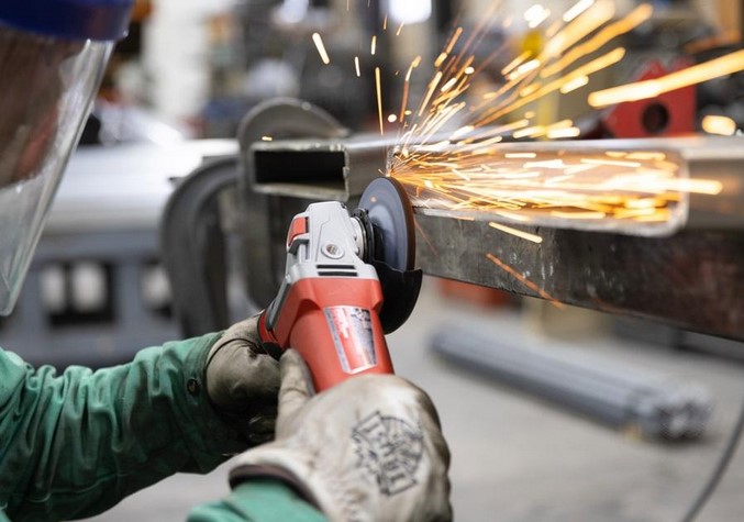
You pull the trigger on your newly purchased angle grinder, ready to slice through an old rusty iron rebar blocking your backyard fence project. The tool screams to life at an incredible 11,000 RPM. You press the spinning edge against the metal, but instead of a clean, fast slice, the tool violently kicks back against your wrists, fills your garage with a cloud of foul-smelling smoke, and the wheel literally shatters into jagged projectiles that fly past your safety glasses.

In my ten-plus years of running fabrication shops and tackling grueling residential renovations, I have witnessed this exact terrifying moment more times than I care to admit. The angle grinder is arguably the most versatile, high-output handheld power tool in existence—but it is also the most unforgiving.

When a project goes wrong, it is almost never the fault of the grinder’s motor itself. The breakdown happens because the operator treated the angle grinder disc as a generic, one-size-fits-all commodity. Matching the exact chemistry, grain structure, and mechanical design of your abrasive wheel to your specific material is the ultimate secret to unlocking commercial-grade performance. Let’s break down the technical physics, metallurgy, and safe operating blueprints required to master your spinning arsenal.

The Physics of High-Speed Friction: Decoding Abrasive Material Science

To understand how a premium angle grinder disc operates, you have to cast aside the idea that the tool cuts like a traditional saw blade. A saw blade relies on sharp, physical teeth to tear chunks out of a material. A grinder disc, on the other hand, relies on micro-fracturing abrasive grains to erode the target material away via intense localized friction.

The Self-Sharpening Illusion

An engineered abrasive wheel is actually designed to systematically break down as you use it. It consists of thousands of microscopic, sharp mineral crystals suspended in a matrix of synthetic resin and fiberglass mesh reinforcement.

As you apply physical pressure, the dulled outer mineral grains fracture away under stress, continuously exposing brand-new, razor-sharp crystal points hidden directly underneath.

Analogi: The Controlled Avalanche Blueprint

Think of a spinning abrasive wheel like a highly controlled, high-speed mountain avalanche. If the snow (the mineral crystals) is packed too loosely, the mountain slides away instantly without doing any work. If the snow is frozen into an unbreakable block of ice, it simply glides smoothly without cutting. A perfect angle grinder disc balances this exact formula—shedding worn material at the exact rate required to maintain a continuous, aggressive bite into the steel.

Selecting Your Spinning Weapon: The Core Disc Categories

Walk into the tooling aisle of any active industrial supply house, and the shear variety of wheels can overwhelm an intermediate builder. For streamlined workshop logistics, we divide these assets into three distinct operational profiles.

+-----------------------------------------------------------------------+
|                    ANGLE GRINDER DISC APPLICATION INDEX               |
+---------------------------+-------------------------------------------+
| Type 1 / Type 41 (Flat)   | Ultra-thin profile, engineered solely for |
|                           | high-velocity linear parting/cutting      |
+---------------------------+-------------------------------------------+
| Type 27 (Depressed Center)| Thick, rigid build, optimized for heavy   |
|                           | surface stock removal and beveling        |
+---------------------------+-------------------------------------------+
| Flap Discs (Overlapped)   | Sanding strips on a backing plate, perfect|
|                           | for paint stripping and weld blending     |
+---------------------------+-------------------------------------------+

1. The Parting Workhorse: Thin Cut-Off Wheels

When your goal is slicing through rebar, structural angle iron, or stainless steel sheets, reach for a Type 1 (or Type 41) flat cut-off wheel. These profiles are engineered to be incredibly thin—frequently measuring a mere .040 to .045 inches in thickness. Because the kerf is so narrow, it displaces minimal metal, keeping heat buildup low and maximizing your cutting velocity.

2. The Metal Shaper: Depressed Center Grinding Wheels

If you need to grind down an ugly, bulging weld bead or bevel a heavy steel plate before welding, a thin cutting wheel will explode under side pressure. You require a heavy-duty Type 27 depressed center wheel, which features a thickness of 1/4 inch. The structural hub is recessed, allowing you to operate the tool at a shallow angle relative to the workpiece without the locking nut scraping across your project face.

3. The Finisher: Multi-Layered Flap Discs

For paint removal, rust remediation, or prepping a surface for high-gloss industrial coatings, standard grinding wheels are way too aggressive. Flap discs feature overlapping rectangular strips of coated abrasive sandpaper arranged radially on a rigid backing plate. They provide a cushioned touch that blends contours beautifully without gouging the underlying metal substrate.

Decoding the Technical Stamp: Reading the Industrial Formula

Every professional angle grinder disc features an alphanumeric code printed directly across its blotter label—such as A24R-BF. Learning to read this code is how you graduate from an amateur to a true tool expert.

       [ MATERIAL ]     [ GRIT SIZE ]     [ HARDNESS ]     [ BOND TYPE ]
            A                24                R                 BF
        (Aluminum         (Coarse /        (Hard Grade     (Resinoid Fiber
         Oxide)          Aggressive)      for Soft Steel)    Reinforced)
  • The Mineral Mineral (A, Z, SG): The first letter denotes the abrasive grain type. A stands for Aluminum Oxide (the baseline standard for everyday carbon steel). Z represents Zirconia Alumina (a rugged, self-sharpening grain engineered for heavy stainless steel fabrication). SG or Ceramic denotes premium micro-crystalline grains that offer the longest lifespan and lowest heat output.

  • The Grit Number (24, 36, 60): Indicates grain size. Lower numbers (24-36) are highly aggressive for rapid material removal. Higher numbers (60-120) are fine grits meant for smooth finishes.

  • The Hardness Rating (G through Z): Represents the bond grade holding the wheel together. Soft bonds (letters like H, I, J) release dull grains quickly, which is perfect for hard metals. Hard bonds (letters like P, Q, R) retain grains longer, optimized for softer metals like mild construction steel.

  • The Matrix Bond (BF): This stands for Resinoid Bonded, Reinforced with Fiberglass mesh. It guarantees the wheel has the structural tensile strength to resist flying apart under extreme centrifugal force.

Step-by-Step Blueprint for Safe, High-Efficiency Operation

Ready to fire up your tool and make some sparks fly? Mount your selected wheel, secure your personal protective equipment (PPE), and follow this precise contractor operational sequence:

  1. The Ring Test Inspection: Before mounting any vitrified or resinoid wheel, tap the disc body lightly with a plastic screwdriver handle. If it emits a clear, metallic ring, the structure is sound. If it makes a dull, hollow thud, it contains an invisible internal fracture and must be discarded immediately.

  2. Match the RPM Ratings: Check the maximum safe operating speed stamped on your angle grinder disc. The disc’s rated RPM must always be higher than the maximum no-load speed of your angle grinder motor. If you put a large 7-inch wheel rated for 8,500 RPM onto a high-speed 4.5-inch grinder spinning at 11,000 RPM, the wheel will literally self-destruct from extreme centrifugal stress.

  3. Establish the Angular Attack: When using a Type 27 grinding wheel, do not hold the tool flat. Maintain an intentional 15-to-30-degree angle relative to your workpiece. This ensures the physical load is carried by the structurally reinforced edge of the disc wheel rather than the weaker center face.

  4. Let the Machine Do the Work: Never slam or violently push a cutting disc into a slot. Maintain a firm, steady pressure, and let the tool’s high RPM establish its own path. Forcing the tool causes the motor to bog down, generates extreme thermal spikes, and induces blade binding.

          [ CORRECT GRINDING POSITION ]
                /
               /   <- Angle Grinder Body (~15-30 Degrees)
              /
         [===/===] <- Angle Grinder Disc Edge
        ------------------------------------
         [   STRUCTURAL METAL WORKPIECE     ]

The Pitfalls that Field Pros Guard Against

The Deadly Aluminum Loading Phenomenon

Many intermediate DIYers grab a standard steel grinding wheel to clean up a piece of scrap aluminum tubing. This is a catastrophic workshop mistake. Aluminum has an incredibly low melting point compared to steel. As you grind, the friction instantly melts the aluminum, loading the soft metal directly into the microscopic pores of your abrasive wheel. Once the pores are completely glazed over with aluminum, the disc can no longer breathe or shed heat. Within seconds, the wheel will undergo a thermal shock explosion, shattering the composite matrix into dangerous shrapnel. Always use a specialized, paraffin-wax coated disc specifically stamped for “Aluminum” or non-ferrous metals.

  • Never Remove the Guard: I see amateurs remove their metal tool guards constantly because they want better visual clarity on a tight joint. Stop doing this immediately. If a cutting wheel binds in a slot and explodes, that guard is the only barrier stopping a piece of fractured fiberglass flying at 200 mph from striking your face.

  • The Storage Trajectory: Abrasive resin bonds are highly sensitive to ambient humidity and chemical vapors. Never stack your wheels loose on a damp basement floor or toss them into a drawer soaked in motor oil. Store your spare inventory completely flat on a dry shelf inside their original cardboard packaging to prevent warping and chemical breakdown.

Conclusion: Command Your Workspace Fabrication

Taking control of your metalworking and home renovation projects with a premium, application-specific angle grinder disc setup completely changes your workshop output. By understanding the metallurgy profiles of your abrasive grains, matching your wheel speed safely to your motor’s output, and utilizing proper grinding angles, you protect your wallet from ruined materials while keeping yourself completely safe from dangerous kickbacks.

Are you preparing to tackle a heavy fabrication project, cut down some old masonry pavers, or prep a steel frame for welding this coming weekend? What specific challenges or near-misses have you experienced with angle grinders in the past? Let me know your project specs or tool questions in the comments section below, and let’s get those sparks flying safely!

Mechanical Assembly Stability: Ensuring Precision with the Clamp Set Spring

Source:https://www.thome-precision.com

You have spent three hours carefully cutting the miters for a custom picture frame. The wood is expensive, the grain is perfectly matched, and you’ve just applied a fresh layer of wood glue. But as you reach for your heavy-duty bar clamps, the joints begin to slide. The glue acts like a lubricant, and before you can tighten the screw, your perfect 90-degree angle has shifted into a messy, lopsided trapezoid.

In my decade of managing high-stakes home renovations, I’ve seen more projects ruined during the “glue-up” phase than during the actual cutting. We often obsess over the power of the table saw, but we forget that Mechanical Assembly Stability depends entirely on how you hold things together. This is where the Clamp Set Spring becomes your most valuable “silent partner” in the workshop. It’s the tool that provides the instant, one-handed grip that saves your sanity when the clock is ticking and the glue is drying.

The Physics of Tension: Why Springs Matter

To understand the beauty of a Clamp Set Spring, you have to understand the difference between “passive” and “active” pressure. A standard C-clamp or bar clamp provides passive pressure; you screw it down, and it stays where you put it. But wood and other materials are organic—they compress and shift.

A spring clamp provides active, constant tension. Think of it like a high-end suspension system on a mountain bike. While a rigid frame might crack under a sudden bump, the suspension absorbs the movement while keeping the tires (or in our case, the wood joints) in constant contact with the ground. When you use a Clamp Set Spring, the tool is “pushing back” against the material with a predictable, calibrated force that doesn’t let up until you release the handle.

The “Third Hand” Insight

Early in my career, I tried to install crown molding solo. I quickly realized that I lacked the three extra hands required to hold the molding, check the level, and fire the nail gun. I started using heavy-duty spring clamps as “stop-blocks.” By clipping a spring clamp just below my layout line, I created a temporary shelf that held the weight of the lumber. That’s the real-world utility of a Clamp Set Spring: it’s not just for holding things together; it’s for holding things in place so you can work accurately.

Engineering the Grip: Anatomy of a Pro-Grade Clamp

Not all spring clamps are created equal. If you buy the cheap, plastic bins at the checkout counter, you’ll find the springs lose their “memory” after just a few uses. For professional-grade Mechanical Assembly Stability, you need to look at the engineering.

1. High-Carbon Steel Coil

The heart of the Clamp Set Spring is the coil itself. Professional sets use high-carbon tempered steel. This ensures that the “clamping force” remains consistent whether it’s the first time you’ve opened the clamp or the ten-thousandth.

2. Pivoting V-Groove Pads

If your clamp has fixed pads, it will only apply pressure at a single point, often causing the tool to “walk” off the workpiece. I always look for sets with pivoting pads. These allow the clamp to adjust to irregular shapes or angled joints, ensuring the pressure is applied perpendicular to the surface.

3. Ergonomic Lever Ratio

A good spring clamp shouldn’t require a grip-strength trainer to operate. The handle length is engineered as a lever. A well-designed Clamp Set Spring maximizes the “mechanical advantage,” allowing you to exert 30 lbs of pressure at the tips with only a fraction of that effort at your palm.

Technical LSI Vocabulary: The Professional Spec Sheet

When you’re browsing for your next Clamp Set Spring, look for these technical markers to ensure you’re getting industrial-quality tooling:

  • Clamping Force (PSI): Measured in pounds per square inch. For delicate trim, you want 10–15 PSI; for structural glue-ups, you may need 30+ PSI.

  • Thermoplastic Rubber (TPR) Grips: Unlike cheap vinyl, TPR won’t slide when your hands are sweaty or covered in sawdust.

  • Throat Depth: This is the distance from the tip of the pad to the spring. A deeper throat allows you to reach further onto a board for better stability.

  • Corrosion Resistance: Look for zinc-plated or powder-coated steel to prevent the spring from rusting in humid garage environments.

Expert Advice: The “Marring” Warning

Here is a piece of advice you won’t find on the packaging: The stronger the spring, the more dangerous the pad.

I’ve seen beginners ruin a soft pine tabletop because the high-tension Clamp Set Spring left a permanent circular “dent” in the wood. This is called marring.

Pro Tip: If you are working with softwoods like pine, cedar, or poplar, always place a small “caul” (a scrap piece of wood) between the clamp pad and your project. This distributes the pressure over a larger surface area and protects your finish.

Never snap a spring clamp shut when it’s empty. The “dry fire” vibration can eventually cause micro-fractures in the pivot pin, leading to a catastrophic failure where the spring flies out at high velocity. Treat them with the same respect you give your power tools.

Strategic Applications in Home Improvement

The Clamp Set Spring isn’t just for woodworking. In my ten years of field experience, I’ve used them for:

  • Electrical Work: Holding a light fixture in place while I wire the ceiling box.

  • Painting: Clipping drop cloths to the top of a ladder to prevent tripping hazards.

  • Plumbing: Holding a P-trap in place while checking the alignment of the slip-nuts.

  • Automotive: Clipping a work light to the underside of a hood.

Analogy: The Clothespeg on Steroids

Think of a spring clamp like a clothespeg, but engineered by NASA. While a clothespeg can hold a shirt on a line, a Clamp Set Spring is designed to fight the physical warping of wood and the gravity of heavy materials. It is the “temporary glue” that allows you to step back, look at your work from a distance, and ensure everything is level before you make it permanent.

Maintaining Your Arsenal

To keep your Clamp Set Spring performing at peak levels, you must manage the friction at the pivot point. Once a year, I apply a single drop of dry PTFE lubricant to the spring coil and the pivot pin. Avoid using grease, as it will attract sawdust and turn into an abrasive paste that eats away at the metal.

If the pads become slick with dried glue, don’t scrape them with a knife—you’ll ruin the grip. Instead, soak the pads in warm soapy water or use a bit of white vinegar to dissolve the wood glue, restoring that “tacky” surface that prevents the clamp from slipping.

Conclusion: The Foundation of Every Accurate Build

Precision isn’t just about how you cut; it’s about how you hold. By integrating a high-quality Clamp Set Spring into your workflow, you transition from “hoping” your joints stay square to “ensuring” they do. It is the cheapest insurance policy you can buy for your hard work and expensive materials.

What’s the one project that almost fell apart because you didn’t have enough hands to hold it? Have you discovered a “weird” use for a spring clamp that saved the day? Share your stories in the comments below—I’m always looking for new ways to put these versatile tools to work!

Mobile Operational Infrastructure: Enhancing Flexibility with the Mobile Workbench Base

Source:https://stackbin.com

You are halfway through a weekend project, mid-rip on a heavy sheet of plywood, when you realize your table saw is pinned against a stack of storage bins in a cramped garage. To move it, you have to lift, grunt, and pray you don’t throw out your back or misalign the fence. Statistics show that the average DIYer spends nearly 20% of their “shop time” just moving equipment and clearing floor space rather than actually building.

In my twelve years of optimizing workshops—from tight single-car garages to expansive industrial bays—I’ve learned that the most valuable square footage is the space that can change at a moment’s notice. The secret isn’t a bigger room; it’s the Mobile Workbench Base. It is the difference between a static storage unit and a dynamic “battle station” that adapts to your workflow.

The Gravity Problem: Why Static Benches Fail

Early in my career, I built a massive, “bomb-proof” workbench. It was beautiful, heavy, and once it was loaded with tools, it was essentially a permanent structural member of the house. I quickly realized that a static bench is like a desktop computer in a world that needs a laptop.

If you are working on a large-scale project—like a dining table or a bathroom vanity—you need to be able to walk around all four sides of the piece. A Mobile Workbench Base provides that “orbital” access. It transforms your heaviest machinery from a liability into an asset that can be tucked away or brought to center stage in seconds.

The Physics of Mobility

Think of your workshop like a game of Tetris. If the pieces are frozen, the game ends quickly as the space fills up. A mobile base acts like the “rotate” function. By lowering wheels or engaging a lever, you negate the friction of 500 pounds of steel and wood, allowing you to rearrange your “operational infrastructure” with the push of a finger.

Engineering the Foundation: What to Look for in a Mobile Workbench Base

When you are shopping for or building a base, you aren’t just looking for “wheels.” You are looking for a mechanical system that balances two contradictory needs: Mobility and Total Rigidity.

1. Load Capacity and Structural Integrity

A standard workbench can easily exceed 300 lbs once you add a vise, hardwood top, and power tools. Your Mobile Workbench Base must be rated for at least 1.5x your estimated weight. Look for heavy-gauge steel construction and reinforced corner brackets to prevent “racking” (the side-to-side swaying that happens when you’re hand-planing or sanding).

2. The Deployment Mechanism: Step-Down vs. Fixed Swivel

There are two primary styles of mobility:

  • Step-Down Casters: These are my personal favorite. The bench sits on its own solid legs until you step on a foot pedal, which engages the wheels. When you “disengage” them, the bench drops back onto its solid feet.

  • Locking Swivel Casters: The wheels are always in contact with the ground, and you click a small tab to lock them. These are great for lighter carts but can feel “spongy” under a heavy miter saw station.

3. Vibration Dampening and Floor Contact

In the world of home improvement, vibration is the enemy of precision. If your base has even a millimeter of “wobble,” your cuts will be off. A high-quality Mobile Workbench Base should offer adjustable leveling feet so you can compensate for uneven garage floors (which are almost always sloped for drainage).

Technical LSI Vocabulary: Mastering the Spec Sheet

To build a truly professional workshop, you need to look past the marketing fluff. Pay attention to these technical specifications:

  • Polyurethane Treads: Unlike hard plastic or rubber, polyurethane wheels won’t “flat spot” over time if left sitting under a heavy load, and they won’t mar your epoxy floor.

  • Total Locking Casters: This means the wheel doesn’t just stop rolling; it stops swiveling. This is crucial for keeping a workbench from “fishtailing” while you apply lateral pressure.

  • Boring Pattern: The hole alignment on the base that allows it to adapt to different leg sizes (4×4 posts vs. metal frames).

  • Center of Gravity (CoG): A mobile base should keep the tool as low to the ground as possible to prevent tipping during transport.

Expert Advice: The “Invisible” Stability Rules

I’ve seen many beginners install a Mobile Workbench Base only to find their bench shaking like an autumn leaf. Here is the Pro Tip that I give to every one of my clients: “Legs over Casters.”

If you are building a custom base, ensure that the weight of the bench is transferred directly through the vertical legs to the floor, rather than hanging off the side of the casters. This is called “Vertical Load Alignment.” When the wheels are retracted, the bench should feel as solid as the foundation of your house.

Beware of “Universal” bases that use thin, stamped metal. While they claim high weight capacities, they often flex under the torque of a table saw motor starting up. Always prioritize a base with a “triangulated” design for maximum torsional rigidity.

Scaling Your Workspace: The Modular Ecosystem

The ultimate goal of using a Mobile Workbench Base is to create a modular ecosystem. In my shop, my table saw, my outfeed table, and my assembly bench are all on identical-height mobile bases.

This allows me to “link” them together to create a massive 8-foot by 12-foot support surface for huge projects, and then break them apart and park them against the wall when I need to pull the car into the garage. This “Scaling Purity” is what separates a cluttered hobbyist corner from a professional-grade production environment.

The Ergonomics of the Foot Pedal

It sounds minor, but the ergonomics of the deployment lever matter. If you have to bend over or use extreme force to lift the bench onto its wheels, you won’t move it as often as you should. Look for a Mobile Workbench Base with a “high-leverage” foot pedal. It should feel like stepping on a heavy-duty stapler—smooth, mechanical, and satisfyingly tactile.

Maintenance: Keeping the Infrastructure Rolling

A workshop is a dusty place. Sawdust is the natural enemy of ball bearings. To ensure your Mobile Workbench Base lasts a decade:

  • Blow it out: Use compressed air to clear dust from the caster swivels once a month.

  • Lubricate: Use a “dry” PTFE spray. Avoid “wet” oils like WD-40, which actually attract dust and turn into a grinding paste inside your bearings.

  • Check the Nuts: The vibration of power tools can loosen the mounting bolts over time. Give them a turn with a wrench every six months.

Conclusion: Take Your Shop for a Spin

Upgrading to a Mobile Workbench Base isn’t just about moving furniture; it’s about reclaiming your creative freedom. It removes the physical barrier between “having a tool” and “using a tool.” When the effort to set up a project drops to zero, your productivity skyrockets.

What is the “anchor” in your shop that you’re tired of moving by hand? Is it a vintage cast-iron jointer or a massive assembly table? Drop a comment below and let’s talk about how to get your heavy hitters rolling!

Advanced Masonry Engineering: Clean Penetration with the Tile Drill Bit

Source:https://www.ceres-tools.com

The sound of a sharp crack is the nightmare of every homeowner and DIY enthusiast. You’ve spent weeks picking out the perfect porcelain tiles for your bathroom backsplash, and you’ve spent even more time meticulously installing them. Now, you just need to drill one small hole for the towel rack. You press the drill trigger, and in a split second, a jagged fracture webs across the entire tile.

I’ve been there. In my first year as a contractor, I ruined a three-hundred-dollar slab of Italian marble because I used a standard masonry bit on a high-speed setting. It was a humbling lesson that taught me one absolute truth: in the world of masonry, the Tile Drill Bit is not just a tool; it is a precision instrument that requires a specific set of engineering principles to master.

The Physics of Penetration: Why Tiles Shatter

To understand how to drill through tile, you have to understand what tile is. Whether it’s ceramic, porcelain, or natural stone, tile is essentially a “frozen liquid” or highly compressed earth. It is incredibly hard but lacks flexibility.

Think of drilling into tile like trying to poke a hole through a sheet of ice with a needle. If you hammer the needle, the ice shatters. If you heat the needle and rotate it slowly with consistent pressure, you melt your way through. Standard masonry bits work by “hammering” the concrete behind the scenes, but when using a Tile Drill Bit, we rely on abrasion and friction management.

Anatomy of the Modern Tile Drill Bit

Not all bits are created equal. Depending on your project, you will likely encounter two main contenders:

  1. Spear-Head Carbide Bits: These look like a tiny spade or arrow. They are fantastic for standard ceramic tiles. The sharpened carbide tip “scrapes” the glaze until it finds purchase in the softer clay body.

  2. Diamond-Tipped Hole Saws: This is the gold standard. Instead of a point, these bits feature a hollow cylinder coated in industrial diamond grit. They don’t “cut” so much as they grind the tile away. This is the only way to tackle modern, ultra-dense porcelain.

Engineering the Perfect Hole: A Step-by-Step Guide

In my ten years of experience, I’ve developed a “Zero-Failure” workflow. If you follow these mechanical steps, you will never crack a tile again.

1. Defeating the Glaze (The “Slippage” Problem)

The biggest hurdle is the smooth, glass-like surface of the tile. Your Tile Drill Bit will want to dance across the surface, scratching everything except where you want the hole.

Pro Tip: Take a piece of heavy-duty masking tape and place an “X” over your mark. This creates just enough friction for the bit to grab hold without wandering. For diamond bits, I often use a plywood template with a pre-drilled hole to act as a guide.

2. The Slow and Steady RPM

Speed is the enemy of masonry. High RPMs generate heat, and heat expands the tile molecules unevenly, leading to stress fractures.

I always tell my apprentices: “Let the diamonds do the work.” You should be running your drill at about 25% to 50% speed. If you see smoke, you’ve already failed the thermal management phase.

3. Thermal Management and Lubrication

Even at low speeds, friction creates intense heat at the tip of the Tile Drill Bit. For porcelain and stone, you must use water. You can buy specialized cooling gels, but a simple spray bottle or a wet sponge held against the bit works wonders. This keeps the carbide or diamond grit from “glazing over” and losing its abrasive edge.

Choosing the Right Hardware for the Job

Tile Material Recommended Bit Type Speed Setting Difficulty Level
Ceramic Carbide Spear-Head Medium-Low Easy
Porcelain Diamond-Tipped Very Low Moderate
Glass Specialized Glass/Tile Bit Very Low Hard
Natural Stone Diamond Hole Saw Low Moderate

Advanced Techniques: The “Angle Entry” Method

When using a diamond-tipped Tile Drill Bit without a pilot center, the bit will jump violently if you try to go in flat. Instead, start the drill at a 45-degree angle.

Once the edge of the bit creates a small “crescent” groove in the tile, slowly tilt the drill upward to 90 degrees while maintaining rotation. This “hinge” technique is how the pros get perfectly centered holes in shower stalls without using bulky guides.

Hidden Warnings: The “Substrate Trap”

Here is something you won’t find in most DIY manuals: The tile isn’t usually the problem; it’s what’s behind it.

If there is a hollow gap (an air pocket) in the thin-set mortar behind your tile, the pressure of the drill will cause the tile to flex into that void and snap. Before you drill, lightly tap the area with the handle of a screwdriver. If it sounds “hollow,” be extremely light with your pressure. You are essentially drilling over a bridge with no support beams.

Expert Advice: Never use the “Hammer” function on your drill when penetrating the tile layer. Only switch to hammer mode once you have completely passed through the tile and are entering the concrete or brick wall behind it. Switching too early is the #1 cause of “exit-side blowouts” where the back of the tile shatters.

Essential LSI Vocabulary for Your Toolkit

To truly master this craft, you need to understand the environment. We aren’t just “making holes.” We are managing Compressive Strength, avoiding Thermal Shock, and ensuring Substrate Integrity.

When shopping for your Tile Drill Bit, look for terms like Vacuum Brazed Diamonds (which last longer) or Asymmetric Carbide Tips (which reduce vibration). These technical specs are the difference between a tool that lasts for one hole and a tool that lasts for a whole bathroom renovation.

Final Inspection

Masonry engineering is about patience over power. By selecting the correct Tile Drill Bit, managing your heat with water, and using the “angle entry” technique, you transform a high-stress task into a routine procedure.

Remember, the goal isn’t just to get through the wall—it’s to leave the surrounding aesthetic untouched. A clean penetration is the hallmark of a true craftsman.

Have you ever encountered a “mystery tile” that seemed impossible to drill through? Or perhaps you’ve discovered a clever way to keep your bits cool? Share your experiences in the comments below—I’d love to hear your “battle stories” from the field!

Operational Hardware Management: Enhancing Productivity with the Magnetic Parts Bowl

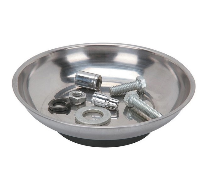
5You’re balanced on a ladder, sweat stinging your eyes, and you finally manage to loosen that stubborn, rusted bolt from the HVAC bracket. You reach for your pocket, but your fingers slip. Clink. Clink. Ping. The sound of a specialized M6 shoulder bolt bouncing off the concrete and disappearing into the abyss of a floor drain or a pile of sawdust is the universal soundtrack of a project gone wrong.

I’ve spent over a decade in the trenches of home renovation—from gutting 1920s kitchens to installing high-end smart home systems—and if there is one thing I’ve learned, it’s that the most expensive tool in your workshop isn’t your miter saw; it’s the time you waste looking for a 5-cent screw.

This is where the Magnetic Parts Bowl moves from being a “neat gadget” to an essential pillar of operational hardware management.

The Chaos of “Table-Top” Organization

Early in my career, I used the “organized pile” method. I’d set screws, washers, and pins on a nearby workbench or, worse, the floor. I thought I was being careful. But a workshop is a dynamic environment. A vibrating power tool, a passing cat, or even the hem of your work pants can turn your organized pile into a scavenger hunt.

Using a Magnetic Parts Bowl is like giving your hardware its own seatbelt. It uses a permanent neodymium or ferrite magnet base to create a localized magnetic field, ensuring that anything made of ferrous metal stays exactly where you put it, even if the bowl is knocked over or mounted vertically.

Why Gravity is Your Enemy (and Magnetism is Your Friend)

Think of your workspace like a busy airport. Your tools are the planes, and your hardware consists of the passengers. If the passengers are wandering aimlessly on the runway, you’re going to have a collision.

A Magnetic Parts Bowl acts as the holding terminal. It centralizes your small components so that your brain can stop scanning the floor and start focusing on the technical task at hand. In the world of professional contracting, we call this reducing cognitive load.

Technical Breakdown: What Makes a Quality Magnetic Parts Bowl?

Not all bowls are created equal. When you’re shopping for this tool, don’t just grab the cheapest one at the checkout counter. Look for these specific technical specs:

1. Material Composition: Stainless Steel vs. Plastic

Most professional-grade bowls are made of Heavy-Duty Polished Stainless Steel. Why? Because it resists corrosion from oils and degreasers, and it won’t crack if you accidentally step on it. Plastic versions exist, but they lack the “heft” required to stay put on a vibrating surface.

2. Magnet Strength and Base Coating

The magnet should be strong enough to hold the bowl—and its contents—upside down on a metal beam. However, the most critical feature is the Rubberized Non-Marring Base.

Pro Insight: Without a rubber coating, the magnet will scratch the paint on your car’s fender or the finish on a new appliance. Always ensure the base is fully shrouded in high-quality rubber.

3. Diameter and Depth

For beginners, a 4-inch or 6-inch diameter bowl is the “Goldilocks” zone. It’s large enough to hold a complete set of engine valve cover bolts but small enough to fit inside your tool bag.

Integrating the Magnetic Parts Bowl into Your Workflow

Operational efficiency isn’t just about having the tool; it’s about how you use it. Here is how I manage hardware on a complex job site:

The “Vertical Mount” Strategy

One of the coolest features of a Magnetic Parts Bowl is that it doesn’t have to sit on a table. Because the magnet is powerful, you can stick it to:

  • The side of a metal toolbox.

  • A vehicle’s frame rail while doing suspension work.

  • The leg of a steel scaffolding unit.

By moving the bowl to eye level, you eliminate the need to bend down, saving your lower back over a long day of work.

Color-Coding and Multi-Bowl Systems

If you are doing a complex teardown—like repairing a washing machine or a deck railing—I recommend using multiple bowls.

  • Bowl A: External housing screws.

  • Bowl B: Internal mechanical fasteners.

  • Bowl C: Electrical connectors and clips.

This “zoning” prevents the dreaded “extra screw syndrome,” where you finish a project only to find three mystery bolts left on the table.

Maintenance and Safety: The “Hidden” Warnings

While it seems like a simple tool, there are a few “gotchas” that I’ve learned the hard way.

  • The Debris Magnet: Your bowl won’t just catch screws; it will catch metal shavings and “swarf.” Over time, this grit builds up on the rubber base and can scratch surfaces. Clean the bottom of your bowl regularly with a microfiber cloth.

  • Electronic Sensitivity: Never place your Magnetic Parts Bowl directly on top of a laptop, a smartphone, or a modern car’s ECU (Engine Control Unit). While the magnetic field is somewhat shielded, it’s still powerful enough to interfere with sensitive Hall-effect sensors or magnetic storage.

  • Non-Ferrous Limitation: Remember, this tool is useless for brass, aluminum, or high-grade 316 stainless steel (which is non-magnetic). If you’re working on a boat or high-end outdoor furniture, test your hardware first.

Efficiency by the Numbers

If you’re a hobbyist, you might think, “Is it really worth $10 to $20?” Let’s look at the data.

In a typical 4-hour repair, the average person spends about 15 minutes looking for misplaced parts, repositioning screws that rolled away, or backtracking because they used the wrong length bolt in a hole. Over a year of weekend projects, that’s 13 hours of lost life. > Expert Advice: A Magnetic Parts Bowl isn’t a storage device; it’s a transit device. Use it to move hardware from the “installed” state to the “ready” state. When the job is done, the bowl should be empty.

The Verdict: A Small Investment for Massive Gains

In the world of Home Improvement, we often obsess over the “big” purchases—the brushless drills, the laser levels, the heavy-duty shop vacs. But your productivity is often dictated by the smallest links in the chain.

The Magnetic Parts Bowl is a low-cost, high-impact solution to one of the oldest problems in craftsmanship: gravity. It turns a chaotic workspace into a streamlined laboratory. It allows you to work faster, stay cleaner, and—most importantly—keep your sanity intact when the pressure is on.

Have you ever lost a “one-of-a-kind” screw in the middle of a project? What’s your go-to method for keeping your hardware organized? Let me know in the comments below—I’d love to hear your workshop horror stories (and how you solved them)!